Symbols and Fills
From Fs_wiki
Contents |
Connective paths
Connecting to Areas
A set of areas are defined by paths (so long as these are not the special centreline or connective style paths). These areas can have symbols placed in or around them by using connective paths that link from nodes on the boundary of an area into the inside of the area. Any other connective path connected to the end node of another connective path will also be associated to the same area, so you can draw in a string of symbols, each connected to the other, and only the first needs to be linked to a boundary node of an area.
We have already seen connective paths associated with an area in the area signals property which was used for defining islands that are areas within another area that represent rock pillars or pitch holes.
Connective paths associated to two areas (Optional, advanced feature)
It is possible for a connective path to be associated to two areas by connecting between two connective paths, each of which is associated to a different area.
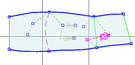
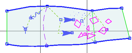
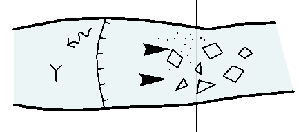
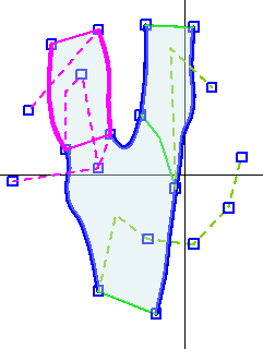
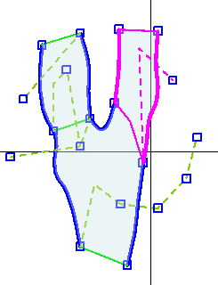
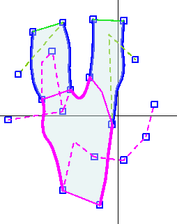
A sketch of connective paths and areas is shown below in three views, one for each area. The connected component of three connective paths on the middle left are associated to two of the areas. This means that if boulders are specified to this connective path, the boulders will spread across both the left and the middle areas.
| 
| 
|
This concept of connective paths associating to more than one area allows us to specify how some symbols and fills can cross boundaries. Note that this is an advanced feature that is not often used! It is usually easier to, instead, simply specify the symbols or fills for each area separately.
Pitches and Ceiling Boundaries
Draw in the pitch boundaries (P path type) and ceiling boundaries (C path type), connecting these either directly to a node on area boundary or to a node connected to an area boundary node (for example, by adding in an invisible line path from the area boundary to where you want your pitch or ceiling path to start. Check that the tick marks by using Detail Render: if you have got the tick marks on the wrong side of the path, select it and click the “Reflect” button (top left of control pane) to reverse the side of the ticks.
Drawing Detail
You might want to draw in some detail “by hand” - for example, individual 3D boulders. To do this, start at a suitable node (e.g., an outer wall, area boundary node) and draw an invisible line to where you want to begin (I line type). Then draw in the boulder or whatever using “D” (for detail) as the line type. For boulders in particular, you may not want these lines to be splined (and so smooth) so turn off splining by selecting “s” at the end of the line types (the last button on W, E, P, C, D, I, N, E, s) so now you get straight lines between each point you click.
Adding Text
Start at a suitable node (e.g., an outer wall, area boundary node) and draw a connective line outside the survey (“N” type, end line with left mouse-shift) then select “Write text” using the left control panel. Put the text (e.g., “?”) in the main box then choose the text type from the dropdown box below (e.g., “qm visible”) then right click back in the sketch to return.
If the text is in the wrong position, you can select the node and click “reflect” in the “Write text” panel, or choose one of the nine buttons to move the text about. Alternatively, you could move the node to which the text is attached by selecting it then creating a new node where you want to shift this node to by left mouse-shift then clicking “fuse” and the original node will be moved to this new position.
Adding Symbols
The symbol button table
Symbols must be associated with a node on a connective path. If you have a connective path selected that doesn't have an Area Signal associated to it already, you can click on the Add Symbols button to show you the list of symbols it is possible to put there. Try clicking on one like breeze or slope. The word appears in the line below so you can see what you have.
Most symbols need only a single click to specify where they should be placed relative to their associated connective path node. These include symbols such as bedrock for which only a single symbol will appear and symbols such as sand, mud, pebbles and boulders which will fill the area surrounding the connective path node.
However other symbols are directional and need two clicks to be specified. These include "arrow" type symbols (breeze, stream and slope symbols, where the first and second click specify the orientation of the symbol) and flowstone (where the symbol fills the area, but again with a particular orientation) and nitrate pits (where the two clicks define the diameter of the pit).
If you want to draw a symbol outside the walls of the passage (for example, a draft arrow), this must first be tied in to an area of the main survey. Do this by starting your connective path from an area boundary (outer wall) node as usual, then click inside the cave area and only then can you do your two clicks wherever you like to specify the draft arrow position.
tutorial out of date from here on. - needs new diagrams - show draft arrow outside sketch
Laying out the symbols
The symbols are not renderable until you click on Update | Update Symbol Lay, which lays them out, checking that they fit and distributing boulder and sand fields randomly. [mention the buttons]
Don't forget to use Auto | Update Areas first to get the areas sorted out right or it won't work.
This is what you should see when you do Update | Update Symbol Lay. Note that the sand is limited to the middle area, while the boulders cross both areas.
See what it's supposed to look like by using Update | Detail Render which makes all the stuff that should be invisible invisible.
Tunnel keeps the data as simple as possible, which is why anything that can be calculated from the data -- such as areas and symbol layouts -- are not stored with the survey. It does mean that on very big surveys it can takes some time to see all of it.
The symbols layout algorithm was upgraded during the houping 2005 expedition. It still doesn't work so well in long thin areas, and will be looked into again at a later date. You should specify symbols as they should be according to your drawings now since, as the software improves, your surveys will be improved too without you needing to do any extra work.
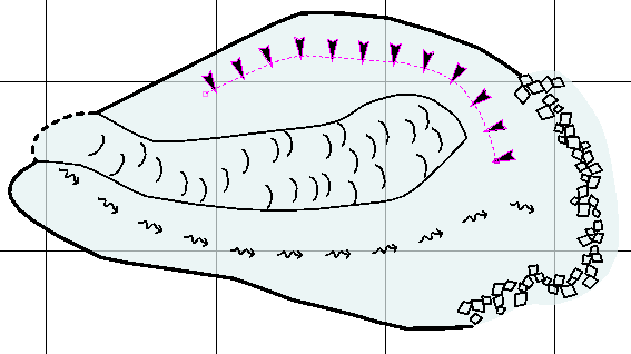
Below is an example of some new symbol layout algorithms that are mostly done. It took only four user specified symbols to make the picture.
What are the symbols?
There are three major directories to the Tunnel installation. The source code is in "src/", the compiled code is in "Tunnel/" and the symbols are in "symbols/".
For further details, see Configuring the symbols xml
Symbol development
Any shape composed of lines, filled areas and words can be used as a symbol. Feel free to define more symbols as necessary. Since they are usually very simple and symetric, don't be discouraged from editing the raw xml code to get it just right. If they are likely to have wide application, they should be uploaded into the standard codebase for everyone's benefit.
Symbol scaling
I will consider putting other types of scaling and transformation into the asymbol definition as users request them. In my opinion it is more aesthetically pleasing to use one of three different fixed-sized slope symbols, say, than make one variable one that can be stretched to all different sizes.
Navigation
- Next Labels and Scalebars
- Up Tutorial
- Previous Tracing the Image
