Tracing the Image
From Fs_wiki
Contents |
Tracing the survey
This is the procedure that was described in the paths section.
Here is a quick recap on instructions.
The importance of connective lines
These may look a bit superfluous at this stage, but the connective lines serve two important purposes. They link the elevation information from the survey data to the passage walls you are drawing, and they tie the walls to the survey centreline so that sketches can be distorted to fit any changes made to the survey data at a later time. The elevation data is used in two ways in Tunnel. Firstly, it is used to decide which passage to draw on top of the other when two passages cross one another (the passage with the higher elevations in the centreline will be drawn over the top of the lower passage). Without the elevation data from the centreline Tunnel will pick one passage at random to be the upper passage. Secondly, you can use the feature to colour the sketch by elevation (select 'Height' on the 'Colour' menu in the sketch window). Tunnel will determine the elevation of each area in the sketch by the elevation of the centreline legs it is connected to via connective lines.
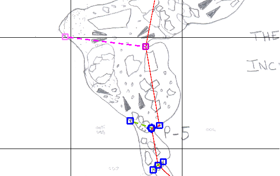
First put in connective lines (N on the control pane) from each, or at least most, of your centreline nodes to the outer walls. If the centreline node is already on the wall this is not necessary but otherwise you would usually add a connective path to each of the two walls. At junctions you might want to add more than two connective paths. Remember that these connective paths do not divide up your survey into areas so it does not matter if these paths cross lots of detail in your drawing.
Tracing in the walls
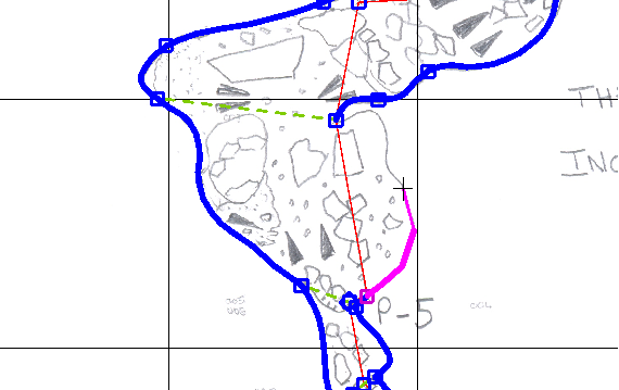
Use left mouse-control to select a pre-existing node (for instance one of the connective path nodes that you just created) or just left mouse alone to create a brand new node. To end a line, use left mouse-shift. Use the control pane to make these wall lines either "W" (for wall; solid) or "E" (for estimated wall, dashed).
Make sure that you always link in properly to existing nodes (for example those created above by the connective lines). BEWARE - it is very easy to accidentally create a new node (left mouse-shift) when actually you meant to join up to a pre-existing node (left mouse-control). This leads to all sorts of grief when you later try to define areas or select nodes as you will now have two nodes nearly on top of each other and it is easy to miss this as it may just look like a single node unless you zoom right in. Two nodes placed near to or on top of one another are drawn as a diamond so you can tell them apart. This may be correct (for example, for a plumb leg) but could also indicate a mistake.
If the Shift left select gets the wrong node, you can move the mouse away and try again and it will cycle to the next one. Or you can zoom in to get it.
Add new, extra nodes if there are any important junctions in the wall that do not already have a node (e.g., pitch boundaries). If you forget to add a node you can add it into a line later by selecting the line then press left mouse-shift-control where you want the new node
Use the estimated wall line type if necessary and then complete any areas using invisible lines (I path type in the control pane). These are used at entrances and where the present drawing ends though the cave continues and where unexplored passage is marked.
Check your areas
Now check that your areas are specified correctly by clicking Update Areas: everything inside your drawing should turn light blue. If this fails, systematically start trying to work out where the problem is: divide your area into half using a temporary invisible line between the two walls. Try Update Areas again - hopefully one half of your area is now blue so the other half is where the problem is. Delete your invisible line and put another one inside the problem half. Keep repeating until you find the error. This is often having two paths that do not actually connect (see above). Alternatively, you may have forgotten to add an invisible line to close off an area where there is an entrance or an unexplored (so open) passage leading off. Note that once you combine your survey from two adjacent drawings you would normally delete the two invisible lines after you have linked up the walls.
If your original drawing is dark it may be hard to see the light blue, in which case de-select Show Background using the Control Pane tab. You can select an individual area by using right mouse-shift.
Adding internal details
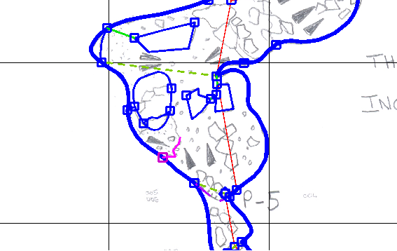
Draw in the pitch boundaries (P path type) and ceiling boundaries (C path type), connecting these either directly to a node on area boundary or to a node connected to an area boundary node (for example, by adding in an invisible line path from the area boundary to where you want your pitch or ceiling path to start. Check that the tick marks by using Detail Render: if you have got the tick marks on the wrong side of the path, select it and click the "Reflect" button (top left of control pane) to reverse the side of the ticks.
Trace in the internal details, connecting things up properly. You may need to insert new nodes, alter the spline-ness (to make lines jagged, not splined, for boulders). Everything can be changed as you go along if you get the linetype wrong. More information on this in later sections.
Rendering your survey
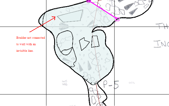
The survey below is shown after using Update Areas then Update Symbol Lay then Detail Render. Make sure all of your sketch area (i.e. the area inside the cave walls) turns blue when you update areas - if it doesn't it means there is a gap in the wall / estimated wall / invisible line around your area.
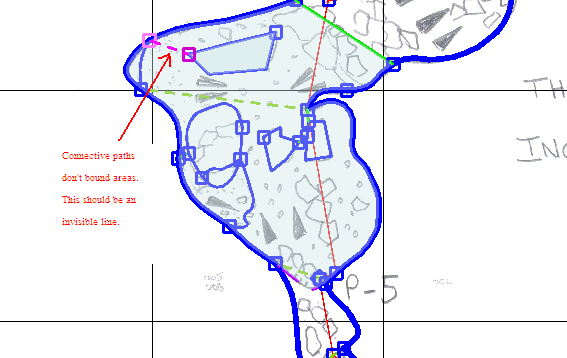
Note that in the example below the area has been closed off at the top with an invisible path (selected in purple). This survey shows a common mistake: the boulder at the top is obscured by the area of the main cave because it is not connected with an invisible line to the outer wall directly (or indirectly, by connecting to another path which is connected to the outer wall).
The image below shows why the mistake with the boulder occurred: the boulder was connected to the outer wall with a connective line type (not an invisible line type). To fix this, simply select this line (so it turns pink) then click on I (for invisible) rather than N (for connective) line type at the top of the control pane.
The final two stages of the rendering sequence (Update Areas then Update Symbol Lay then Detail Render) may be quite slow for large surveys of several kilometres of passage. Note too that these last two steps only create the symbols for the section of your sketch that you are currently looking at in your sketch window. If you want symbols to be rendered over the entire survey you have to zoom out so all of the survey fits in your window (the Update Areas button works for the whole survey, even the bits not currently visible). You can omit the Update Symbol Lay stage and go straight to Detail Render but then if you have changed something (e.g., lines that create a new area) this 't be updated so you won't get to see any changes you have made within that area. To get out of Detail Render so you can continue working on the sketch, use right-mouse to click anywhere in the sketch.
Your main priority should be to get the connections right so that the areas work. Everything else is just decoration.
Adding another background scan
Once you have completed adding all the information from one drawing of your original survey notes you can open up your next drawing (using Add Image). You can switch between your first and this subsequent scans by selecting the scan you want as background using the drop-down box just above "show background". This is useful when you want to toggle between two different drawings to work out how they join up properly.
Navigation
- Next Symbols and Labels
- Up Tutorial
- Previous Positioning the Background
