Positioning the Background
From Fs_wiki
This is normally what you do before you draw anything. However, since it relies on some mastery of the basics, it is being introduced at this stage.
The following example of how we position the image which you want to trace against the centreline uses subsurvey inlet7-11 from the inlet7 cave example you can download from the front page. You will also need to have downloaded the rawscans of the inlet7 survey as well and unzipped them into the same directory.
Contents |
Loading the centreline
Select File | New Empty Sketch from the menubar on the List Sketches window to make a fresh sketch window.
NOTE: Due to bugs in the example survex data, you will need to edit all the .svx files in the directories under inlet7 to comment out the date and export lines before this data will work. You need to comment out all export and date commands by starting these lines with a semi-colon. (e.g. Change any line starting with *export to ;*export and any lines starting with *date to ;*date ). Save all the SVX files before importing the data.
Go to this empty sketch in the View Sketch window and select Import | Import Survex File on the top menubar. Select the inlet7.svx file from the inlet7 example data you downloaded.
The survey data is imported and attached as a label to a connective line which appears in the shape of a letter 'S' in you sketch. Now select Import | Import Centreline from the menus. The survey centreline should be displayed in the sketch window as red lines. (The 'S' shaped connective line must be selected (shown in pink) before you attempt to import the centreline. Select it by right-clicking on it if not already selected). You can right-click on one of the centrelines to see its start and end stations, or use Display | Station Names from the menus to show all the station names.
Survex integration
Tunnel itself doesn't have the ability to do loop closures. However, since the underlying survey data (in the files marked SVX) is completely compatible with Survex, it is able to call that program if it is installed on your computer and use its calculations. More information is given at the bottom of this link in the Loop Closures section.
Loading the image
Select the background tab in the Left Hand Panel of the View Sketch Window, and click on the Add Image button. This brings up a File Dialog Box. Find the directory called "inlet7rawscans" which you should have downloaded and unzipped, select the file "inlet7-11.jpg" and open it. This drawing will now appear as your background.
You can use the Show Background tick-box to hide or display the background image. The same tick-box is available in the Display menu.
The name of the file will be in a drop-down box just above the Shift Ground button. You can add more than one image and use this to select between them. This makes it possible to sketch surveys which span more than one sheet of paper. Once you have added an image, it will always be available in the drop-down box, at the same position and scale as you last saved it.
[The add image stem filing isn't working!]
Shifting the image
The background image starts out centred in the window, and you need to move it to the correct orientation so that it lines up with the centreline of Tunnel.
We use the exact same procedure as for View shifting, except we apply it to the image rather than the view on the screen.
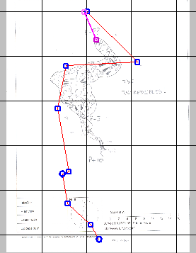
Make a two point path anywhere on the screen (Left Mouse Click, then a second Left Mouse Click while holding the Shift key down). If it is selected (drawn in pink) you can click on the Shift Ground button to translate the scanned survey in the direction of the line.
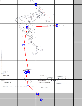
The first thing to do is to move your drawing so that one survey station in the drawing is now in the right place with respect to the Tunnel survey (ignoring the fact that everything else is wrong), like so:
|
|
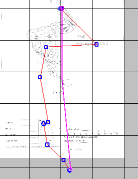
Now we can use a three-point path to get the rest of the drawing to line up. Left Mouse click on top of the survey station on the drawing that is in the correct place, Left Mouse Click again on a different survey station in the drawing that is in the wrong place, and then Shift Left Mouse Click on the centreline node which corresponds to the that same survey station.
Now click on the Shift Ground button.
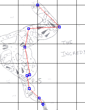
The image will rotate and zoom around the first point in order to move the second point onto the third, like so:
|
|
It is best to choose two survey stations about as far away as possible on your drawing to do this for greatest acccuracy. It is normal to have to move and scale your drawing approximately at first, and then zoom in to the two survey stations a second time to get the points to line up as well as they possibly can before doing a final Shift Ground. You can use the Middle Mouse Button to zoom and translate the view even when you are in the middle of drawing a path.
Moving the centreline
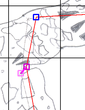
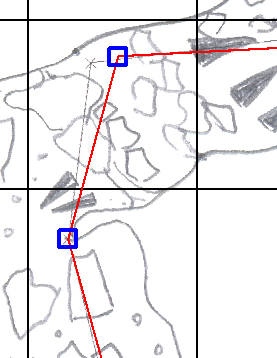
Sometimes it is impossible to get the centreline to match perfectly with the drawing, particularly if the drawing was not done on a computer print-out or if you had a distorted scan of your drawing. When this happens you can use Fuse actions to move individual nodes of the centreline to the right place on the drawing (Control Left Mouse Click on the node, Shift Left Mouse Click on the corresponding point in the drawing, then click on the Fuse button), like so:
|
|
You are supposed to create an accurate representation of the scanned drawing, including all its centrelines. It is easier to start off with a sketch containing the accurate locations of the centrelines and move them to fit the diagram, than to draw them fresh and mark up all the station names.
Once you have all the information transcribed, you will be able to distort this sketch according to how the centrelines have been moved so that it is corrected.
This will be done by creating a new sketch containing the centrelines in their right places, and copying/importing this drawn sketch into it. The process works by encoding your sketch relative to its centrelines, and then regenerating it around the correct centrelines.
- See Importing sketches.
Navigation
- Next Tracing the Image
- Up Tutorial
- Previous Making and Filling Areas
