Drawing and Linking Paths
From Fs_wiki
Contents |
Paths everywhere
Everything you draw in Tunnel is a path: the lines in the sketch, the boundaries to areas, the text labels, and positions of the symbols. For paths to be joined into areas they must connected at their end nodes.
For this lesson you will need a clear piece of sketch. Either slide the drawings of the current sketch out of the way by dragging with the Middle Mouse Button while holding the Shift key down, or create a new sketch by clicking Tunnel | New Empty Sketch on the menubar of the MainBox.
Drawing your first path
Use your Left Mouse Button to click somewhere in the white space of the Sketch Area (graph paper space). Now click (don't drag!) a sequence of points to make a nice wavy path.
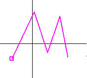
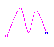
To finish the path, hold the Shift key down when you make your final point with the Left Mouse Button. Your path should now be free (no longer attached to the mouse pointer), and pink (to show it is selected). Notice the little square node marker at either end. The first node is dark pink, and the last node is light pink to show you the orientation. The orientation can be reversed by clicking on the Reflect button in the Control Pane, or using Action | Reflect from the menubar.
Try making several more paths to give yourself something to play with.
Notice that the path goes smooth (or splined) every time you finish it. This smoothing is on by default because jagged paths (for example used for drawing boulder outlines) are less common. You can turn off splining by selecting the small s button.
- Selecting paths
- Clicking with the Right Mouse Button on or near the path of your choice. The selected path is drawn pink. If paths are so close together that you get the wrong one, click again to cycle through to the one you want.
- Deselecting paths
- Click on the Deselect in the Control Pane, use Action | Deselect from the menubar, or Right Mouse Click somewhere nowhere near another path.
- Deleting paths
- Click on the Delete or use Action | Delete from the menubar to remove a path that is selected (drawn in pink). If you are drawing a path and want to take back one node, click on the Back button or use Action | Back from the menunbar.
Different types of path
Changing the path style: Paths can be drawn in several different styles. You can change the style of any path after it is drawn it by selecting it (Right Mouse Click on it so it goes pink) and changing its style by clicking on one of these buttons, or selecting its type from the drop-down box shown below:
The path styles in Tunnel are as follows:
| Wall | W | A thick path used for the outer boundary of the cave. |
| Est. Wall | E | A dashed version of the wall path denoting that its shape is estimated. |
| Pitch Bound | P | A path with tick marks to the side denoting a sudden drop. |
| Ceiling Bound | C | Like a pitch bound, but dashed because it's a ceiling feature. |
| Detail | D | A thin path for internal details like boulder outlines or puddles. |
| Invisible | I | Use this to specify a boundary that you do not want to appear in the drawn-up survey, like the boundary around an area of sand. |
| Connective | N | A special path that connects the survey together and positions symbols and text. Has no effect on the area structure. |
| Filled | F | For solid filled areas. Limited use in some symbols. |
| Splined | 'S' | A substyle applied to any path. It is on by default, so paths are smoothed. Click it to disable it to make jagged paths. |
| Centreline | Used for the survey legs and not drawable by hand. |
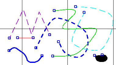
Here is an example of all the different path styles in one sketch. The colours are used to distinguish them while you are editing; they don't show in the final result.
- Smoothed paths
- The [S] at the end of the row of buttons is not really a path style, but a path property which sets or unsets its spline state. Try it on any selected line and it will change between smooth and jagged. Most of the time you will want smoothed lines, which is why it comes on by default.
- Stroke thicknesses
- Change the overall thicknesses of all your paths using Action | Stroke >> or Action | Stroke from the menubar, or click on the buttons in the Control Pane.
Detail rendering
- Most of the time you will be drawing in sketch mode; this shows plane lines, drawn in different colours depending on there type, lines that should be invisible are green.
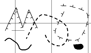
To preview the final output, click on the 'Detail Render' button on the Control Pane. Everything should go black-and-white, the invisible lines will no longer be visible, and the pitch and ceiling boundaries will be drawn properly as follows:
This mode reverts back to normal as soon as you perform any action, like draw a path or move the view. Alternatively, click 'View | Redraw' on the menu.
- Reminder
- if you get the side-dashes the wrong way round on a pitch or ceiling bound, select the path and click on the 'Reflect' button, and try again.
Joining paths
VERY IMPORTANT. For your drawing to work properly it is *essential* that your paths join up perfectly so that the computer can put them together into areas. It may be obvious to a human what is inside or outside of the passages on a cave survey, but a computer isn't smart enough to work it out without help.
For the following exercises begin with no paths selected. Either use the Deselect button on the Control Pane, or click with the Right Mouse Button in some empty region of the sketch.
Recall that you made a path on its own by clicking the Left Mouse Button anywhere on the sketch, then clicking several points in the middle until you ended by holding the Shift key down during the final click.
Starting a path on a node
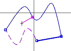
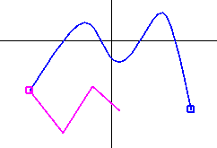
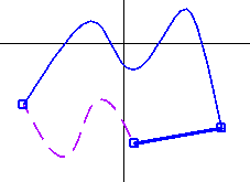
Hold the Control key down (the one below the Shift key) when you first press (and hold) the Left Mouse Button somewhere in the Sketch Area... Nothing will happen, UNLESS the mouse pointer was close to or within one of those little squares at the end of a path when you clicked it down, in which case the square shows up pink.
If you drag (ie move the mouse pointer away while still holding down the button) the pinkness disappears. If you release the button when the square is pink, you create the beginning of a path that is attached to that node.
Ending a path on a node
To end on another node you need to hold the Control key down again when you click the pointer on that final node.
| 
|
Inserting a node into a path
If two paths are to be connected this must be at a node common to both of them. To do this, you must break the first path in two at the point you want it to join to the new, second path and insert a node at the breakpoint. To do this, select the first path (Right Mouse click on the path so it goes pink), and then hold both the Shift and Control keys down at the same time as you click with the Left Mouse button on the place in this first path which you want to break. This will insert a new node at this point and also start a new, second path beginning at this new node. If you only want the node and not the new path, simply click the Delete button to delete the second path.
Merging paths across a node
You can select two paths in a sequence (connected end to end at a node) by Right Mouse clicking on the first on so that it is selected, and then holding the control button down when you Right Mouse click on the second one. If no other paths join to that node, and both paths have the same style, you can click 'Action | Fuse' from the menu (or use the 'Fuse' button on the Control Pane) to join the paths into one. This undoes the inserting a node feature.
Fuse actions
There are several miscellaneous actions that are controlled by paths because they are a useful way of specifying positions.
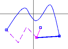
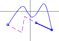
Fusing along a line: If you start a path on a node and end it somewhere else without any segments in the middle (so it's a straight line) and you keep the line selected, you can use the 'Action | Fuse' command on the menu to shift the node from the start to the end. All the other paths connected to that node get distorted in the process.
| 
|
|
The selected line is "Fused" in the right hand picture. Note how the paths connecting to it are distorted, and that the dragging goes from the pink node to the blue node. | |
View shifting
If you draw a path that is a single line anywhere and use Action | Shift View from the menubar while it is selected, it will be deleted and the view will be translated as though you had dragged it along the length and direction of the line.
A more powerful version works for a two-line path -- made with three single mouse clicks, the final one with the Shift key held down. When you use Action | Shift View with a two-line/three-point path selected, the view rotates and zooms in the following way: The first point remains stationary while the view rotates and expands/contracts about that point so that the second point is moved onto the third. You can use the ShiftGround tab in the Control Pane instead of Action | Shift View.
You might need to use View | Upright from the menubar to get it back to normal if you don't want to carrying seeing everything askew.
These shifting features are most useful for Positioning and Tracing Images, rather than your view of the sketch.
The Info tab
Since all of your drawing ultimately has to be saved into a file, it's helpful to be able to see how it will look so that you know what information is retained in the file, and what is forgotten. It's been the policy up till now to save as little as possible, and recreate all the information (areas, symbol layouts) that can be made from it. This makes it much easier to change what the program does over the years, since the programmers knew they weren't going to get the design remotely right first time.
At the bottom of the left hand control pane is a series of tabs: subsets, background, and info. If you select the info panel and then select a path in the sketch, it will print in the textbox exactly how the data for that path will will look in the saved file.
The coordinates are multiplied by a factor of 10 and the y-direction is inverted. This is because the java graphics library assumes the origin is at the top left hand corner, and the fonts (what is used to draw the labels) only works within an allowable range. Decimetres (tenths of a metre) are on the order of magnitude of pixels in most scales, so it works.
The X: and Y: labels at the bottom of the pane show you where your mouse is in real space.
Creating paths to coordinates
If you are in the middle of drawing a new path, or you don't have any selected, the text area is editable. If you type in a series of numbers (delimeted by spaces, commas or newlines) and click on Add Path Nodes, points at those pairs of locations will appear in the current path as if you had clicked on them with your mouse.
Navigation
- Next Making and Filling Areas
- Up Tutorial
- Previous Viewing and Zooming Sketches
