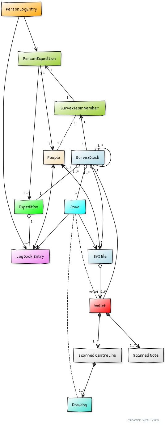
This shows the major "things" in troggle and how they relate to each other.
So a survex (SVX) file is dated to a particular day during the expedition and usually has between 1 and 3 people associated with it.
A Logbook entry has several people involved and may relate to a cave. It will be dated to a day during the expedition.
Although the volume of data in troggle is small, the complexity is significantly intricate that "modern" (i.e. from the mid 1990s) system design tools are compact and useful.
Analysis of expo and design of troggle is done using three levels:
As anyone reading this has probably been on expo and you might think that we can skip the real-world level. Not so: the multiplicities and cardinalities (the number of participants in the association) of the relationships between the different cave survey artefacts can be surprising. See the diagram above: a Wallet can be associated with more than one Survex file, and a Survex File can be associated with more than one Wallet.
The specification level is where the action is. This is where we decide which aspects of the real world we will ignore and what extra concepts we need to make things work.
So we ignore who is resident at top-camp (even though today we record this religiously because of the tax implications for the GastHof at base). We do need to track the in-computer associations between survex files: the *include tree, what directories they live in, what wallet-directory they relate to, and all the individual survex blocks of survey measurements within each survex file.
We only need implementation-level diagrams for tiny, tricky issues. Python is very clear so serves as its own implementation specification. However Django does need some explanation even to a competent python programmer if they have not used it before.
For a fundamental background to system specification the classic work of Cook and Daniels (online PDF, 400 pages) cannot easily be improved upon (start reading at page 10, second paragraph).
A Class Diagram is one the the basic types of structural diagram (as opposed to behavioral diagrams) used to understand complex systems.
The purpose of class diagram is to model the static view of an application: the unchanging structure.
Class diagrams describe structure, but there are useful diagrams that describe behaviour too. Not much of our process is complicated enough to need them though.
The wallet lifecycle is a "interaction" diagram showing the states and transitions between the states for a plastic wallet holding original caving notes and the software equivalent directory. The wallet process is a "sequence" diagram showing which actors (people) interact with a wallet during its lifecycle: inserting pages from the waterproof notebook, taking the notes and sketches and scanning the, processing the survey data to produce centreline plots etc.
The hand-drawn sketch title "Packages" on the troggle architecture page is a UML "deployment" diagram.
See Fowlers pages on UML for more examples of UML in use.
The Class diagram on this page was created online using the YUML free software at https://yuml.me//. Or there is a yUML extension to VScode which can generate the diagram within VScode.
You can edit your own version to revise this when it becomes outdated.
This is the entire source code that generates the diagram:
// Troggle Class Diagram
// ---------------------

// 2025-02-06 Philip Sargent

// Chain elements like this
[SVX file{bg:lightblue}]<>-wallet 1..*>[Wallet{bg:red}]++-1..*>[Scanned Note]
[Wallet]++-1..*>[Scanned CentreLine]
[Wallet]++-0..*>[Electronic data]

[Scanned CentreLine]++-1..*>[Drawing{bg:turquoise}]

[People{bg:wheat}]<->[LogBook Entry{bg:violet}]

[People{bg:wheat}]0..1<->0..1[Users{bg:cyan}]

[Users]1<->0..1[Signups{bg:red}]
[Signups]<->[PersonExpedition{bg:yellowgreen}]

[Cave{bg:cyan}]->[LogBook Entry]

[Cave]->[SVX file]

// note:
[Cave]-.-[Drawing{bg:turquoise}]


[Cave]-.-[Wallet]

[Expedition{bg:green}]1<>-1..*[LogBook Entry]

[SurvexBlock{bg:lightblue}]1<>-1..*[SVX file]

[SurvexBlock{bg:lightblue}]1<>-1..*[Wallet]

[SurvexBlock{bg:lightblue}]1..*<>-1[Cave]

[SurvexBlock{bg:lightblue}]1..*<>-1[Expedition]

[SurvexBlock{bg:lightblue}]1..*<>-1[SurvexBlock]


[PersonExpedition{bg:yellowgreen}]1->1[People{bg:wheat}]

[PersonExpedition{bg:yellowgreen}]1<-1[SurvexTeamMember{bg:yellowgreen}]

[PersonLogEntry{bg:orange}]->[LogBook Entry{bg:violet}]

[PersonLogEntry{bg:orange}]->[PersonExpedition]

[SurvexTeamMember{bg:yellowgreen}]1-.-1[People{bg:wheat}]

[SurvexTeamMember{bg:yellowgreen}]1<-1[SurvexBlock]

[Expedition]1..*<-1[PersonExpedition{bg:yellowgreen}]
From Cook and Daniels (online PDF, 400 pages, pp10-11):
"In this book we present three kinds of object-oriented model. The first kind, which we call the essential model, considers the model to be a description of some real or imaginary situation, which may or may not contain software. We use the word situation rather than system because ‘system’ has so many possible meanings including the software we may be trying to build, and rather than world to emphasise that we are considering purposeful systems situated in a context rather than trying to describe all of some supposedly objective reality. The purpose of building the essential model is to understand and establish the facts about this situation. The building blocks which we use to build essential models are objects (actually object types) and events (actually event types). An essential model is built by drawing annotated diagrams, and interpreted as descriptions of sets, functions and sequences with meanings in the situation being described.
In the second kind of model, called the specification model, we are concerned with specifying software. To create a specification model it is necessary to establish which parts of the overall situation will be implemented in software. In some cases this might be a large part of the situation, whereas in others it might not be a part at all. The activity of specifying exactly what is to be implemented in software is quite different from the activity of establishing the facts about the overall situation; however both of these activities would conventionally fall under the heading of ‘analysis’. Like essential models, specification models deal with objects and events and are built by drawing annotated diagrams. They are interpreted as a description of the abstract stimulus–response behaviour of the software. The specification model describes software at a high level of abstraction, and in particular says nothing about internal sequencing or concurrency. An important part of building a specification model is the allocation among object types of responsibility for aspects of software behaviour.
The third kind of model, the implementation model, is concerned with establishing patterns of control flow within the software. In this model we take into account the fact that computer programs have a limited number of well-defined flows of control, which execute at a finite speed. The building blocks for implementation models are objects and messages. Object interactions are described as messages sent from one object to another, and the implementation model describes message sequencing and concurrency control. Annotated diagrams are used again, although in the implementation model our repertoire of diagrams is richer than for the other kinds of model."