A walk through tunnel - Symbols
From Fs_wiki
As we said before Tunnel comes with a predefined set of symbols.
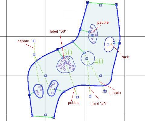
Symbols can be attached to areas using a connective path.
This path must start at a node of the border of the area, and
the first segment must head towards the inside of the area,
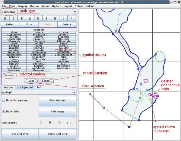
as in the picture below. When you have such a path the "Symbol"
button becomes active. If you click it the list of available symbols
is shown. You can attach one or more symbols to the dangling end of the
path. Use the button "Clear" to clear the list of symbols you have
selected. Use "Cancel" to cancel the action and go back to the
main panel.
Symbols are described by XML files in the "gsymbols" directory. They are not automatically rendered in the drawing. To render symbols, you must "Update | Areas" (either by using the menu or with the button), and must click on the button "Update Symbol" (or the menu "Update | Symbol lay").
Alternatively, you can also click on the menu "Update | Everything", this updates in the order, the nodes heights, the areas and the symbols layout.
Connective paths can be joined among themselves, forming graphs of connective paths. For example, a connective path can come out of a contour node of an area, and two other connective paths can be attached to its dangling end-node. Then you can add a symbol to one of them and a label text to the other: the symbol and the label will be associated to the area. Signals should be added only to connective paths attached to the contour of the area.
A second example consists of having two connective paths coming out of two contour nodes of two distinct areas, attached one to the other at their end-nodes. Next, a third connective path is attached to this node, with a symbol at its other end-node: the symbol is associated to both areas.
A third example is when you have a connective path attached at a contour node of an area, with a symbol at its dangling end-node, and a second connective path starting at this node and with some text at its other end node.
Lastly if you have two connective path attached to contour nodes of two different areas, and attached together at their other nodes, and a third connective path coming out from this node with a signal at its other end-node, then the signal is associated to both areas.
We will talk more about these and other features of connective path when we move to a cave project example.
So far we have prepared three areas for the chokes of blocks. It is time to fill them with the symbols of blocks. Draw a connective path beginning at a node on the border of the area and with the first segment heading into the area. It will appear as a dashed pink line: dashed means that it is a connective path. It is pink because it is the current path. End it somewhere in the area. The three buttons "Add symbol", "Area signal", and "Write text", which were usually grey, will become active. It means that you can attach a symbol, or a signal or some text to the dangling end of the path, and associate it to the area.
Since we are interested in symbols right now, click on the "Add symbol" button (or the menu "Action | Add symbol"). The symbol panel will open up. Click on the "10boulder" symbol button to add. You can add more than one symbol: add also a "5boulder". You will see the string that lists both symbols "10boulder+5boulder". At the same time, the symbol will appear in the drawing.
When you have added enough symbols, start a new path for the next area. You can add more connective paths with symbols into the same area.
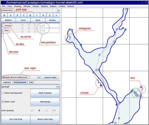
When you are done with the boulders you can move on to the "stream" in the squeeze. Notice that the "stream" symbol has an orientation: it points towards the dangling node of the connective path. If you reverse the path it will point towards the node attached to the contour of the area. Keep this in mind and draw the last (or the first) segment of the connective path in the direction you want to draw the stream symbol. Furthermore, the connective path for the stream symbol ends outside the cave passage: the symbol will be drawn outside of it. Next, put a stalagmite symbol in the passage to the west. The stream and the stalagmite symbols will appear in the picture below.
Attach a question mark text to the choke on the north. Select the "Write text" button (or the menu "Action | Write text"), and enter your text, ie, "?". You can select the style with the dropdown option list. The style choice goes from the smallest ("default" and "qm") to the largest ("area" and "cave"). You can also decide whether to show an arrow (aligned to the connective path: use the "Reflect" button to reverse the direction of the arrow), and whether to put a box around the text. There are nine buttons to determine the position of the text; if the displacements of one unit are not enough, you can type in larger values (in the picture below we typed a displacement of -2).
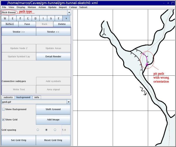
Finally, let's add a label for the entrance, and put two pit paths for the drops. First, we need to insert points in wall paths, ie, split them. When you draw the pit path, it is displayed as a dashed line. You will see the ticks only when you update (menu "Update | Update everything") your sketch. If the ticks are on the wrong side, you must reverse the path with the button "Reflect" (or the menu "Action | Reflect"). In the picture below, the current path has been drawn in the wrong direction and needs to be reversed.
Now our piece of cave starts looking really nice. This is all for the moment. Time to take a rest. In the next chapter we will tackle the whole cave.
If you want, you can read the appendix about creating a new symbol \ref{m_03a.htm app. 3.a}, however you can safely skip it and come back to it when you need.


