A walk through tunnel - Your first sketch
From Fs_wiki
It's now time to make your first sketch.
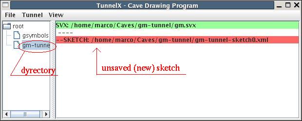
Click on the menu "Tunnel | New sketch". Two things will happen.
A new sketch file will appear in the right section of the MainBox
window. It has a red background to remind you that it needs to be saved.
Its name is built by appending the string "-sketchX" to the directory name,
where "X" is an increasing number starting from 0.
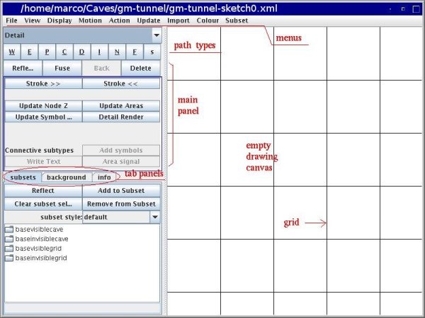
The other thing is that the Tunnel drawing window will popup. You use this window to draw your sketches. The full pathname of the sketch file appears in the title bar of the drawing window.
Before we start drawing the map, let us talk a little bit about Tunnel approach for drawing. In Tunnel, there are three classes of drawing objects:
- nodes: points where you can put symbols or labels, points through which the line of a wall must go, etc. Points are important to mark special positions on the paths. Nodes are shown on the canvas as small boxes.
- paths: the lines that make the drawing; points have no dimension so they cannot be drawn, paths are 1-dimensional and are drawn on the map. A path is a curve which joins two or more nodes. A path can form either an open curve (with two distinct end-nodes) or a closed curve (thw end-nodes coincide). Paths that share a node are connected.
- area: A region on the map sorrounded by a sequence of connected paths that form a closed contour.
How do you draw a path ? Simply by clicking on the points where you want it to go through. However, there must be a way to tell Tunnel that the point you are going to click is the end of the path, otherwise you cannot ever end any path.
Tunnel makes extensive use of combination of mouse buttons and Shift|Control keys to qualify the actions. It takes a while to get used to it, but you will find that it has a very consistent scheme:
| mouse button | = | shift | ctrl | shift+ctrl |
|---|---|---|---|---|
| left | input a node | input the final node | attach at an existing node (initial or final) | insert a node in a path |
| middle | rotate (if enabled) | move the drawing | zoom the drawing | |
| right | select a path | select an area | continue a path selection |
Shifts and zooms can also be obtained with the submenu of the "View": "Up", "Down", "Left", and "Right" for the shifts. "Scale up" and "Scale down" for the zoom. Notice that the rotation is by default disabled. To enable it, click on the menu "Motion | Enable rotate". Rotation might put the drawing into an incomprehensible position: clicking on the menu "View | Upright" will revert the drawing in the proper upright position.
There are three other submenus of the "View" which come useful:
- "Max" displays the drawing with the maximun extent;
- "Center" positions it at the center of the drawing area;
- "Redraw" redraws the sketch in drawing mode, after a "Detail render".
Now just try and draw a path. Click here and there on the canvas on the right.
The nodes are displayed as little squares, and they are joined by straight
lines. Everything is pink to denote that it is the active object, the one you
are working on. Finish your path holding the Shift key pressed down while
you click on the final point.
You can erase the active path clicking on the "Delete" button on the left. Alternately you can select the menu "Action | Delete", or press the key combination (shortcut) "Ctrl D". If you want to erase the last point you have drawn, click on the "Back" button (or the menu "Action | Back").
By default the last path you have drawn is the current path, the one that has the focus of the actions. You can change the current path by selecting another with the mouse selection operations (right button). You can deselect the current path, and have no path selected, by clicking the menu "Action | Deselect".
Get acquainted with the Tunnel drawing interface:
- draw a few paths,
- start a path at the endnode of another path (use the Ctrl key),
- end a path at the endnode of another path (again Ctrl key).
- shift the drawing (Shift and middle mouse button),
- zoom in and out (Ctrl and middle mouse button),
- select a path (right mouse button),
- erase the selected path ("Delete" button, or menu "Action | Delete", or Ctrl-Delete keys).
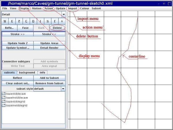
You are ready for the map now. Clear the canvas by erasing all the paths you have drawn in your experiment. We want to draw the cave walls using the centerline as a reference. Click on the menu "Import | Centerline". The survey centerline will appear in the drawing canvas (as in the picture below). Using the menu "Display", you can select whether to display the following items:
- the centerline;
- the stations names;
- the stations altitudes;
- the nodes, both for the centerline and for the paths;
- the background (this is controlled also by the "show background" toggle in the "background" tab-panel);
- the grid (this is also controlled with the "show grid" toggle in the "background" tab-panel);
- the transitive subset; TODO
- the inverse subset; TODO
- the depth colours; TODO
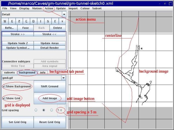
You need to draw the cave wall around the centerline, the same way you would do on a piece of paper. With Tunnel, you can load the scanned cave drawing as a background and use it as a guide for your drawing. Click on "Action | Add Image" (or swicth to the "background" tab and click on the button "Add Image"). Select the scanned image through the file dialog interface, and click "OK" to confirm. In this example you can use the file "gm0.gif". The background image will appear under the centerline. You can hide/show it by toggling the "Show Background" checkbox in the "background" tab.
The background will probably not fit with the centerline. Since the latter is your reference, you must move and stretch the background to fit with the centerline. Tunnel provides two powerful actions to achieve this.
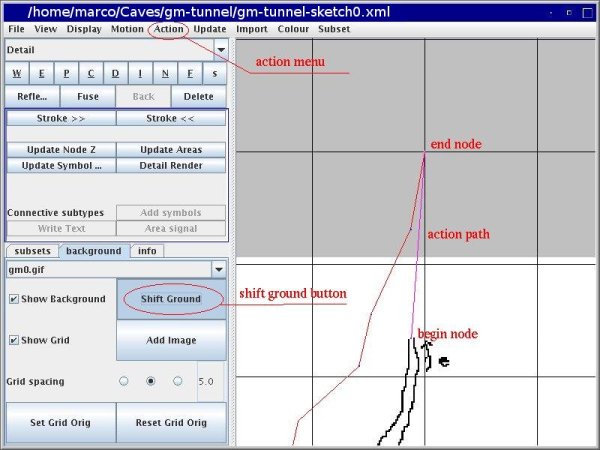
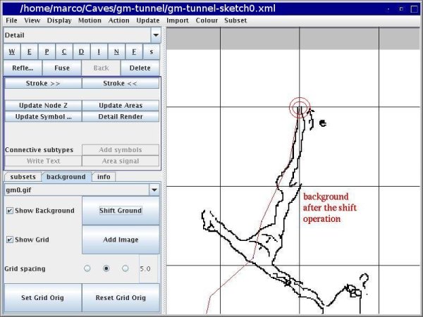
The first action allows you to shift the background, taking a point of it into a specific point on the drawing window. To do this you must draw a two-point path (a straight line) from the point of the background to the corresponding position on the drawing window where you want to move it. Then click on the button "Shift Ground" (in the "background" tab), or the menu "Action | Shift ground". In the images below, the drawing has been previously shifted and zoomed (middle mouse button and Shift or Ctlr keys) to bring the relevant part at the center of the canvas. The first image shows the path from the point on the background to the point on the first station. The second image shows the result of the action.
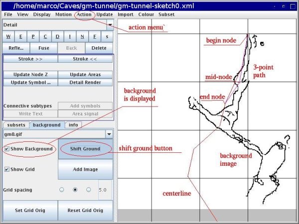
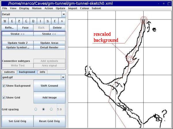
Now one point on the background is correctly referenced (with respect to the centerline), but the image is rotated and has a different scale. It is necessary to rotate and rescale it. Here is where the second path action comes into play. This uses a three-point path. The first node is at a point which is held fixed (the center of rotation and rescaling). The second node is at a point on the background that will be brought on the position, in the drawing, of the third node. In the process the background image is rotated and rescaled.
At this point a portion of the scanned cave drawing is referenced with the centerline and you can start drawing the walls. Start a path clicking at a point, then click on other points along the wall; hold the "Shift" key to click on the final point.
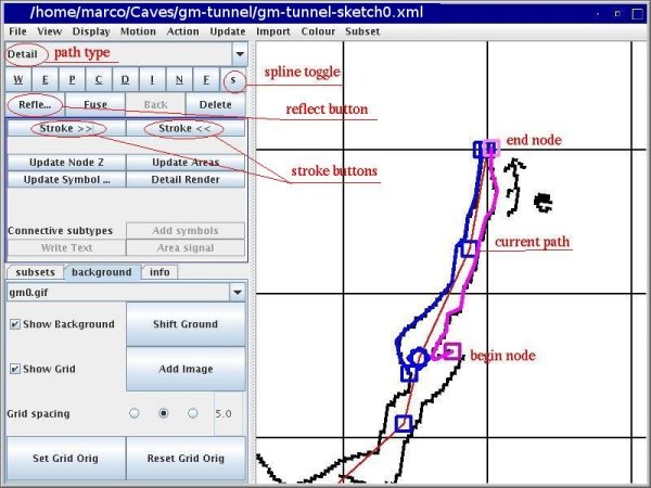
Draw the walls now. You can change the thickness of the paths with the buttons "Stroke \gt \gt" (thicker lines) and "Stroke \lt \lt" (thinner lines), or the analogous "Action | Stroke" menus. In the picture below the line width has been over-emphasized just to show the work. First we drew the wall at the left from the top down, then the wall on the right from the bottom up. Paths have orientation: the begin-node is darker, and the end-node is lighter. You can reverse the orientation of the active path clicking the button "Reflect" or with the menu "Action | Reflect". Path orientation is important for the contour of pits and chimneys.
Now you can continue with the following portions of the cave wall. First adjust the background to the centerline, in the region you are about to draw, then draw the wall paths. Remember that you can start a path from a new node, or you can attach it to the end point of an existing path (using the "Ctrl" key). When you draw the walls it is often convenient to attach the paths together.
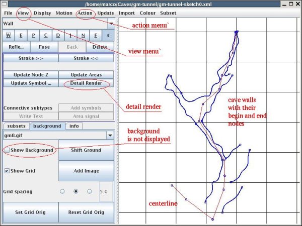
Here is our final drawing, without showing the background (toggle the "Show background" button or click on the menu "Display | Show background"), and with the grid (toggle the "Show grid" button, or click on the menu "Display | Show grid"). There are three radio buttons in the "background" tab to select the grid spacing. In the image below it is set to an intermediate value (5 meters in this case).
You can preview how the map will look like, clicking the button "Detail Render" (or the menu "Action | Detail Render"). Tunnel reverts to the work display as soon as you click any other button (or you can click the menu "View | Redraw").
You can save the map as image file with the menu "File | Export bitmap". Do it now, and check the resulting image with an image viewer program. Probably it is not very impressive, but this is the first result you obtained with Tunnel. The important point is that the information to draw the image are contained in the XML sketch file(s) you created with Tunnel, and can easily be updated at any time.
You can export the map also in SVG format. Select the menu "File | export svg". The file "ssvg.svg" will be created in the "tunnelx" directory.
Go to the MainBox window and save your work now. Click on the menu "File | Save XML dir". The sketch0 file will turn green to show that the file on the disk is in line with that in the memory.
You can now exit Tunnel and have some rest.
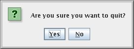
When you exit Tunnel it asks you if you really want to quit.
It does not tell you whether there are unsaved changes.
You can see that from the MainBox window: if no file is red there is no
need to save modified data.
Beware that if you click on the button "yes" and there
are red files, your work will be lost.
In the next chapter, we will see how to add features to our cave map. And make it really look like what you get with a hand-drawing.
