Making and Filling Areas
From Fs_wiki
Contents |
Making Areas
Areas are used for filling your survey with colour and for laying out symbols such as sand and boulders. Areas are not saved with your data, so they need to be generated every time you load your surveys from disk, using the 'Update Areas' button on the Control Pane of 'Update | Update Areas'. The areas also need to be recalculated after drawing and deleting paths in the sketch since they are not updated automatically.
The algorithm
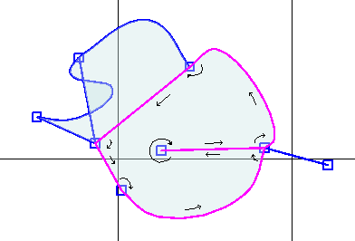
The algorithm to generate the areas is simple: Follow a path until it hits the first node. If there are other paths that connect to that node, choose the first path on the left (clockwise), and follow it until it reaches another node. (If there are no paths connecting to that node, go back on the same path in the opposite direction.) Repeat until you reach the starting path (going in the same direction). This series of paths defines one area. Continue until all areas are accounted for.
The reason this algorithm is important is that it explains why it matters that the paths connect correctly. If, say, there is a little kink in a path just as it reaches a node causing it to connect from the "wrong" angle, the areas won't form as you would expect. Sometimes you have to zoom far in and make the strokes thinner (using the 'Stroke <<' button) in order to see the mistake. Another common problem is not having the two ends of a path connecting to a single node (you may accidentally have created two nodes very close to each other and the path leaves from one and returns to the other leaving a small gap inbetween. Again, you may need to zoom right in to see this, as the two nodes might be almost on top of each other. Be careful about linking nodes properly when you create your paths.
Generating Areas
After you click 'Update | Update Areas' on the menu (or use the 'Update Areas' button in the Control Pane), the areas will be filled with a light shade of blue. You can also select areas by holding the shift key down when you click the Right Mouse button in the area.
If you then click the on 'Import | Stripe Areas' in the menu, the areas will get hatched so that you can see them much more clearly. This is a useful feature when looking for problems in your sketch. As you gain practice mistakes become rare, but early on they can be very frustrating when you can't find them.
The feature of being able to select more than one path at a time (holding the control down when you Right Mouse click on the next path) only works if paths are properly connected at their ends.
Connective paths don't form areas
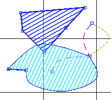
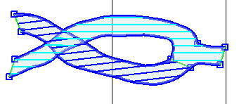
The area generating algorithm ignores centreline and connective style paths. In the picture above, the dotted green path is connective, so it doesn't bound the third area on the right. The fact that connective paths don't interfere with the mosaic of areas makes them very useful for other purposes, such as holding labels, setting the types of areas, and laying out symbols.
The centreline paths (the lines representing the survey legs) also don't do anything to areas. Survey legs are often long and can cross many areas. They rarely have anything to do with the structure of the cave beyond the relative offsets of some fixed points.
Islands in an area
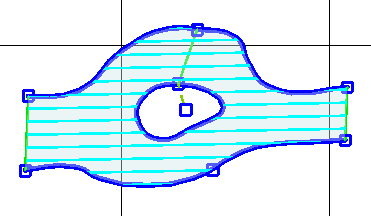
Sometimes areas need holes in them where there is a rock pillar or pitch in the middle of the passage.
Connecting the Islands
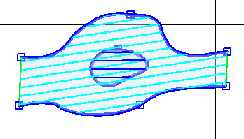
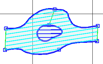
Islands must be connected to the outermost cave wall because otherwise the area surrounding them will fill inside the island (as in the diagram above) whereas in fact the area within the island should be part of the outside rock, not part of the cave. This is one of the uses of the Invisible path style.
Area Signals
Once you have only one area being drawn where you do not want it instead of two (as in the diagram above), it is easier to suppress it. Draw a Connective style path into the inside of the island and select this path. Three buttons in the Control Pane will become active (non-greyed). Click on the one that says 'Area signal' and that whole sub-panel will change to the "Area Signals" panel. Click on the drop-down box that says 'plan' and change it to read 'rock'. The other two "Area Signals" are hole (for a pitch in the floor that drops into a lower chamber), and verysteep (for a wall that covers a significal horizontal extent, like in a hading rift).
Now click on the 'Update Areas' button to see the change.
Overlapping areas
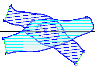
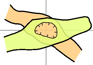
While it is, in theory, possible for one area to overlap itself, it will not render properly, so the area should be broken up with an invisible path. We will look at the problem of how to get the areas drawing in the correct order (from bottom to top) by using connections to the centreline later.
Here is an example demonstrating a pitch hole instead of a rock pillar. We cannot guarantee the areas will be drawn in the right order until we start using the centrelines.
Difficult cases
The guidelines for cave survey drawing are incomplete and you will find instances where there appears to be no way to express what you know is in the cave on the paper. To use a computer to do part of the work (such as filling in areas and laying out symbols), you have to draw your cave surveys to a level of consistency that is not necessary when using paper and ink.
Undercut pitch bounds
The worst cases come from pitch boundaries that have passages leading off from underneath. Usually it is best to draw such cases as two unconnected areas rather than have an area on either side of the pitch bound as you do when there is no undercut. But the solution is unsatisfactory, especially when the undercutting passage is smaller than the horizontal extent of the pitch boundary.
There is a feature reached by the menu command 'Action | Pitch Undercut' which makes a duplicate of a Pitch Bound in the form of an Invisible path, and connects the end points with two zero-length connective paths with a dropdown Area Signal. However, it is beyond the scope of the current tutorial to explain further.
Navigation
- Next Positioning the Background
- Up Tutorial
- Previous Drawing and Linking Paths
