One Quick Example2
From Fs_wiki
Contents |
Drawing the cave outline
Now we are ready to start drawing the cave outline, meaning the passage walls. You may find that the sketch you have loaded is not possible to perfectly align to the entire survey centre line at once. This is probably due to distortion introduced in the process of printing the centreline from survex, drawing on it and scanning it back in. Printers and scanners rarely reproduce the perfect geometry of an original document due to paper shinkage and imperfections in the devices. This is not a problem, as we can just align the piece of the centre line which we are going to draw around first, and then realign the scanned sketch to each section of the survey as we go.
|
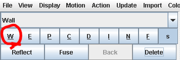
Select line type 'Walls' (W on the sketch window buttons), and then start to draw the passage walls along the survey centre line for the section of passage you are working on.
|
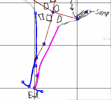
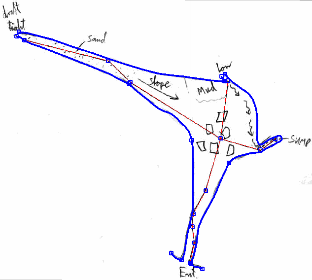
Here we have drawn the entrance passage. Note that the lines are drawn as smooth curves. Where we want sharp bends in the lines at the entrance, we have ended the wall lines and started new lines at the same nodes. You must take care to join each line onto the last using the node which ended the previous line, by holding the CTRL key while clicking on the node to start the new line. If the lines are not joined at the node then you will have two nodes one on top of the other (indicated by one node square being shown rotated 45 degrees on top of the other, so that both nodes are visible). The lines need to be joined at the nodes in order to define areas, which will be important when we come to add symbols to the drawing. Now finish drawing all the cave walls. Remember to realign the sketch to the section of centreline you are drawing along if the scanned sketch is not properly aligned across the whole survey.
|
Defining Areas
Now that the main passage walls are drawn, we need to define areas. Areas are spaces on the drawing completely enclosed by lines. At the moment we have no areas defined because our passage walls are not connected across the cave entrance or across the ends of two possible continuations of passages marked tight and low on the original sketch. Areas are important for a number of reasons. They define where symbols should be drawn on the survey. They can be coloured differently according to which part of the cave they belong to. They can be marked as being inside or outside the cave (i.e. solid rock inside a loop of cave passages should not be coloured as cave passage.
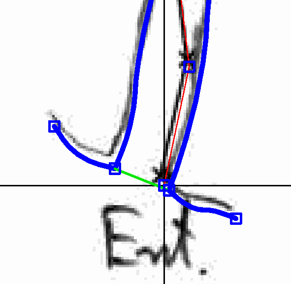
We are first going to close the gaps between our wall lines to make the entire cave one area. We do not want the lines which join the ends of the walls to appear on the survey, so we will draw them using the invisible line type. Invisible lines are shown in green on the drawing during editing. Select the invisible line type, and draw a line which connects across the entrance. Make sure it is joined properly to the nodes on the wall lines by starting and ending the line while holding down the CTRL key. Take extra care to join the invisible line to the node on the wall line, and not the nearby node on the survey centreline. You will see the node you are about to join onto coloured pink when you hold down the left mouse button with CTRL pressed to start or end the line. If the wrong node is highlighted pink then move the mouse pointer away from it before taking your finger off the mouse button to stop the line being linked to the wrong node.
|
Now add invisible lines across the ends of the other two open passages so that all the lines forming the perimeter of the cave are joined to each other. This should have created an area. Confirm this by clicking the 'Update Areas' button on the control pane of the sketching window. If your area if properly defined then you should see the background of the areas is coloured a faint blue, and the passage wall lines are coloured with dark and light blue to show which side is on the inside of the area, and which is on the outside.
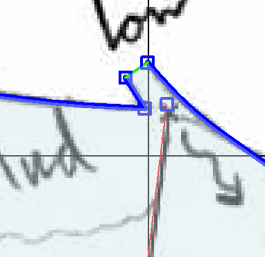
|
You can see the areas in your drawing more clearly by selecting Stripe Areas from the Display menu on the sketch window. This will temporarily highlight all areas with stripes.
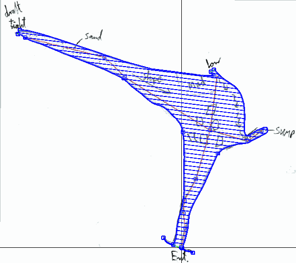
|
Attaching the Centreline to the Walls
It is important to attach the centreline of your survey to the walls of the cave you are sketching. This serves two purposes. Firstly it allows Tunnel to determine the elevation of the areas of the cave from the elevation of the survey station on the cave centreline they are attached to. This is used to determine which areas should appear on top of others when passages cross over or under each other. Secondly, it allows Tunnel to move the sketch with the centreline when corrections are made to the survey data which cause the centreline to move. This is one of the most powerful features of Tunnel. It will distort your sketch to match the new position of the centreline if you correct an error in the survey data, or close a loop which shifts the centreline to distribute the loop closure error around the loop.
The centreline is attached to the cave walls using connective lines. This line type is selected using the N button in the line types selector. But we need nodes on the walls to attach to the survey station nodes on the centreline. Normally I stop and restart a wall line at a node adjacent to each station on the centreline as I am drawing them (as this saves time overall), but here we have drawn the walls without doing this, so we have to insert nodes into the walls. This is done as follows. First select the wall line you want to add the node to by right-clicking on it. Then hold both the CTRL and SHIFT keys down at the same time and left-click on the wall line at the point you want to add a node. You will now have a line starting from the new node, so hold CTRL and left-click on the centreline node you want to end the line at to attach the centreline to the wall. This new line type will be a wall line because it was a wall we selected when we started it, so click the N button to switch to the connective line type before deselecting the new line.
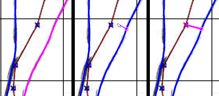
|
Repeat this process to attach all the centreline nodes to points on the walls nearest to them as shown here. Don't forget to attach points from both walls of a passage to each centreline node.
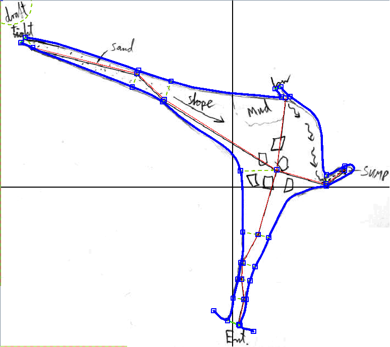
|
To do
- Adding Symbols
- Adding labels
- Rendering the Drawing
Navigation
- Next Drawing Up Your Own Survey
- Up Tutorial
- Previous One_Quick_Example
