One Quick Example
From Fs_wiki
(This is a work in progress. Please feel free to correct any factual errors or embelish any points which are not clear enough).
This section of the tutorial will walk you through the drawing up of a complete cave survey using Tunnel. This might seem like it should be at the start of the tutorial, but it is important that you already understand how to manage survey data and use the drawing tools in Tunnel. So if you have skipped those sections of the tutorial you should go and read them first, do some practise drawing and then come back here.
Contents |
Before You Start
Before you can start to draw up a survey, you will need the following:
- The survey data for the cave (in the form of a Survex data file).
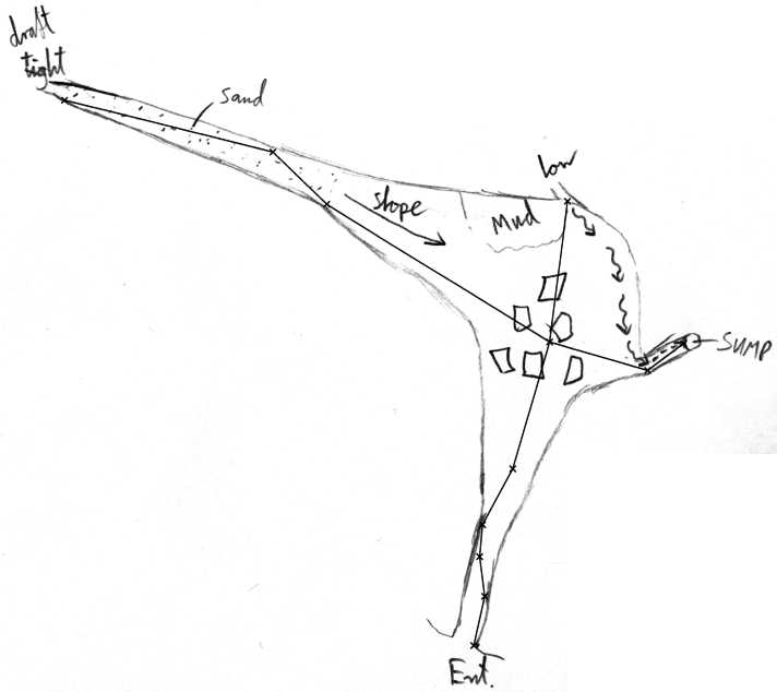
- A plan sketch of the cave survey done to scale over the cave centreline, scanned in as a bitmap file (PNG, JPEG, BMP, GIF).
You might have several sketches of different parts of the cave. We will assume for this simple example that you only have the one sketch.
This example will use the following items, which you can copy off this page to use too if you do not have your own data at this time. (Save the data in a file named 'examplecave.svx' and right-click on the sketch image to save it to your disk).
*begin examplecave
*entrance 001
*fix 001 3234 4231 352

;Cave: Made up example cave for Tunnel Quick Example
;Date: 11/05/2006 Footleg

;From To Tape Compass Clino  L R U D
001 002 3.28 012 -25  ;0 0 0 0
002 003 2.33 353 -2  ;0 0 0 0
003 004 1.88 005 0  ;0 0 0 0
004 005 3.73 028 +6  ;0 0 0 0
005 006 9.59 016 +36  ;0 0 0 0
006 007 17.44 302 +29  ;0 0 0 0
007 008 4.34 314 +2  ;0 0 0 0
008 009 12.42 284 +4  ;0 0 0 0
006 010 5.98 106 -8  ;0 0 0 0
010 011 2.64 053 -2  ;0 0 0 0
006 012 8.42 007 +7  ;0 0 0 0

*end examplecave
|
Example Cave Sketch
Starting A New Tunnel Project
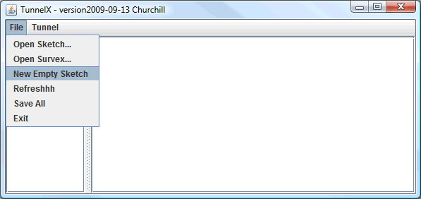
Now we are ready to start using Tunnel. Launch the Tunnel application (or if you already have it running then select New Empty Sketch from the File menu in the List Sketches Window.
|
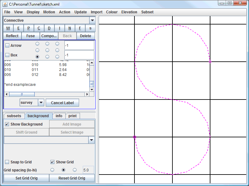
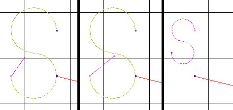
Now select Import Survex File from the Import menu in the sketching window and browse to the location of your Survex data file. (We will be using ExampleCave.svx). You do not need to put this file in any special location, as Tunnel will create a copy of all the data in it. You should now see you imported data attached to a connective line in the shape of an 'S' as shown below.
|
It is a good idea to save your new sketch at this point to create a new sketch file before starting the drawing. Select Save as... from the File menu in the sketching window to do this. You should now be able to see your sketch file listed in the main box window. Next time you run Tunnel you can open your sketch by selecting Open sketch... from the File menu and browse to the location of your sketch file. You can then double-click on the sketch file listed in the main box window to open it in the sketching window.
- Tip: Once I have a project set up with all my sketches in the same directory, I create a copy of the r.bat file which I use to start Tunnel, and add the path to the project folder to it. Save this file as r_examplecave.bat and you can now start Tunnel with your project opened automatically each time you come to work on it.
Creating A Plan Sketch
Now we are ready to start drawing our survey plan view in Tunnel. If not already open, load your sketch file and open it in the sketching window. We will be working in the sketching window for the rest of this tutorial example. Just remember to save your changes using File/Save before you exit Tunnel (you can save an individual sketch from the sketching window, or save all edited sketches from the File List window).
You can resize the sketch window to make it as large as your screen. This will make it easier to work for you, but I will be keeping the sketch window small for this example so that the screen shots are not too large for the web pages.
Importing the centreline
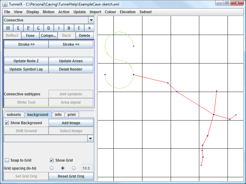
Select the 'S' shaped connective line with the right mouse button to highlight it in pink, then click Import Centreline from the Import menu in the sketch window. This will import your cave survey centreline data into the sketch. You should see the centreline displayed as a set of red paths with blue nodes at the path ends (corresponding to each survey station).
|
In this case the connective line is a bit in the way of our sketch. We can move it by holding CTRL and clicking on one of the blue end nodes of the 'S' shaped line to start a new line from that node. Then SHIFT click in the location you would like to move this node to (it will draw a line from the old to the new position you want the node). Then click the Fuse button to move the node. This will shrink the 'S' so that it does not get in the way of our sketch. This is the standard process to move any node in a Tunnel sketch.
|
Loading the background sketch
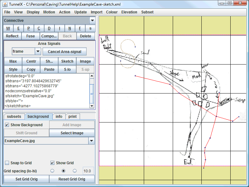
Next we need to import our scale drawing of the cave corresponding to this centreline data. Look at the bottom half of the left pane of the sketch window, and you will see a set of tabs. The background tab is already selected in our previous screenshot. Select the background tab, and you will see a set of buttons and tick boxes relating to the drawing background.
Right-click anywhere on the sketch background to deselect everything. Check that the Show Background checkbox is ticked on the background tab. Then click the Add Image button in this pane, and browse to the location of your scanned survey plan sketch. Select the image file which contains your scanned sketch and select Open. You should now see your image displayed under the centreline data in the sketch window.
|
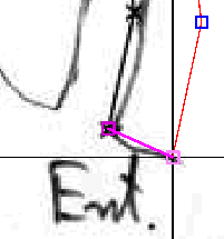
Note that the scanned drawing is not correctly aligned to the cave centreline data. We need to align it by using paths. First pick a point on the background drawing that corresponds to one of the points on the centreline. Draw a straight 2 node path which starts at this point on the background drawing and ends at the position of the actual centreline node which the point should be aligned with. It is best to zoom in on the sketch to do this more accurately. (If you do not know how to zoom and pan the sketch, or draw paths, then you should have read the earlier sections of this tutorial as suggested at the start of this example!).
Remember to hold down the CTRL key rather than the SHIFT key to end a path at an existing node (in this case the centreline node).
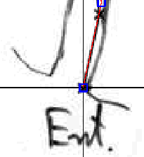
Now with this path still selected, click the Shift Ground button in the left pane to move the background drawing so that the two points at the ends of the path are aligned one on top of the other.
|
|
Now zoom out so you can see the whole sketch. You will see that we have aligned the drawing with the centreline at one point. Now we need to scale and rotate the drawing so that it is completely aligned with the centreline data. This is done by drawing a 3 node path. The first node should be the point where the drawing and centreline are already aligned. The second node should be a different point on the background drawing which needs to be aligned to another survey station. The final node should be the survey station on the centreline which needs to be aligned to the second point.
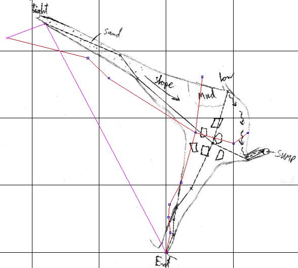
|
- Note: I have rotated the sketch slightly in this screenshot to show more clearly where the middle node is on the 3 node path.
Click the Shift Ground button again with this 3 node path selected, and the background drawing should be properly aligned with the centreline data.
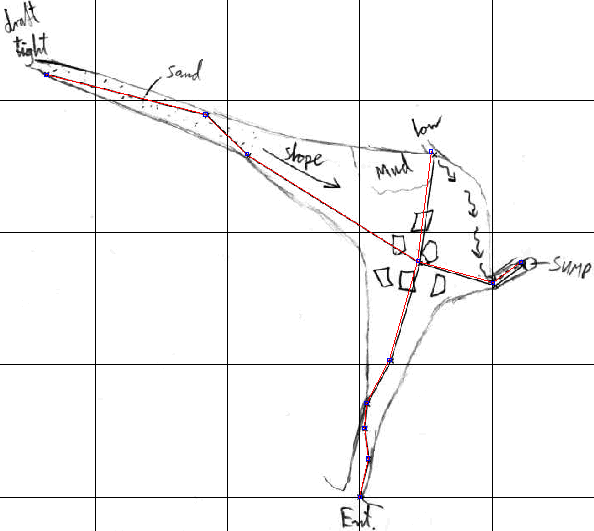
|
Reopening a sketch
Just a quick note at this stage about how to get back to where you left off if you close Tunnel and reopen is again at a later time. By default the background sketch will not be displayed, but there will be a rectangle indicating a background sketch was loaded. You need to make sure this rectangle is in the area visible in the sketch window and then the sketch bitmap file name will be listed in the drop down list on the background tab. Select it as shown here and it will be displayed. This is how you pick which bitmap to display when you have loaded more than one into a larger cave sketch.
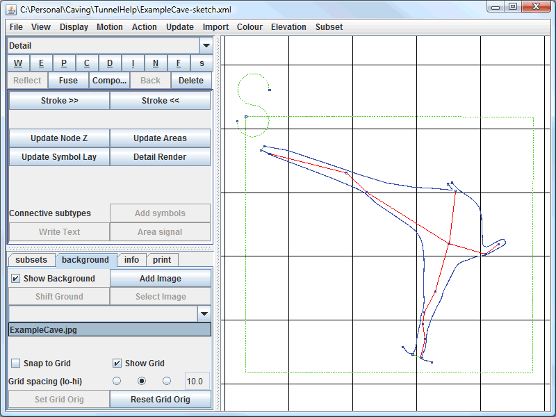
|
Now we are ready to start drawing the cave.
Navigation
- Next One_Quick_Example2
- Up Tutorial
- Previous Symbols and Labels
